Call us today Tel: 001 -
RSSUS Services Inc.
Part of Risk Security Services US Inc
RSS in Partnership with Seward Safety
Seaward Safety keeping you compliant

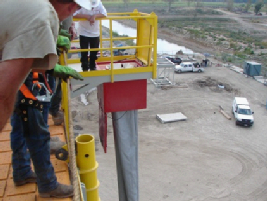
Petrochemical Plants Vertical and Slide Escape Chutes
SPECIFICATION VERTICAL THREE LAYERED CHUTE SYSTEM
Industrial Vertical Escape Chute System is a floor mounted evacuation system designed to be installed in a cut-
The DM-
For severe weather environments the system can be fitted with electrical heat tracing to ensure availability on demand even in the harshest of conditions.
1.0 DESCRIPTION OF SYSTEM
The system is comprised the following main components:
Qty 1 x Chute container with lower trap door, hinged lid and hydraulic dampened arms. The chute container depth (excluding the lid) can vary dependent upon the length of chute required to be packed inside, however the standard dimensions are:
890mm x 890mm x 1219mmH (35’’ x 35’’ x 48’’H). Height can vary dependent on control tower chute height.
Three Layered Vertical Escape Chute designed to support a dead weight of 2 tonnes. Heat resistant to 600o C, melting point 800o C. The chute length varies dependent upon the height of the control tower above the deck exit location. Note: 1 meter air gap is required at the bottom for evacuees to exit
2.0 Chute Container
The system is comprised a deck mounted chute container into which the chute, is packed. The container is fabricated from powder coated mild steel.
The main chute container is painted red with the lower trap door safety yellow and red chevrons and the words ‘Escape Chute’. In all cases an epoxy three coat preparation and painting system is provided with supporting fabrication and painting certificates, metal mill test reports, welding certs, UV and UT reports provided. All paint applications are suitable for offshore marine environments.
The deck mountable chute container requires a cut out of approx. 900m x 900m (35.4” X 35.4”) or fits into a deck mounted support frame (supplied as an option by RSS and has a hydraulically dampened lid and lower trap door. The lid assembly is safety yellow and decaled with red chevrons and the wording ‘Escape Chute’. A serial number identification plate is provided and lists the system serial/model number with the date of manufacturer and RSS emergency contact telephone numbers.
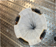
3.0 Vertical Three Layer Chute
Layered Vertical Escape Chute designed to support a dead weight of 2 tones and heat resistant to 650 degrees with a melting point of 800 degrees. The Chute length varies dependent on operating height; however in all cases a one meter air gap is required at deck level for evacuees to exit the chute.
Layer 1
The outer ‘Flame-
There is a space between the outer and middle layer designed to reduce the radiated heat transferred to the middle & inner chute layers.
Layer 2
The middle ‘braking’ layer, this is fitted with a series of stainless steel coiled springs sewn into the material. These springs have a small diameter designed arrest descent as the individual descends. Descent speed through the chute is adjusted by the individual extending or withdrawing arms & legs.
The evacuee only needs to apply pressure on the chute's interior wall with legs and arms, the more pressure, the more you slow down, less pressure and you will speed up. In all cases descent speed is controlled and safe.
Layer 3:
The Inner Layer -
4.0 Material Specification
INNER CHUTE LAYER:
MATERIAL : Polyester
WARP : Polyester
Breaking Tenacity : 185.2 Tensile Strength (Kgf) (C.R.E. Grab Method)
Breaking Tenacity : 82.7 Tearing Strength (Kgf) (C.R.W. Tongue Method)
Flame Resistant : None
Decomposing Temperature : 260 Degrees "C"
WEFT : Polyester
Breaking Tenacity : 184.9 Tensile Strength (Kgf) (C.R.E. Grab Method)
Breaking Tenacity : 80.4 Tearing Strength (Kgf) (C.R.W. Tongue Method)
Flame Resistant : None
Decomposing Temperature : 260 Degrees "C“
MIDDLE CHUTE LAYER:
MATERIAL : Nylon 1901
WARP : Nylon 1901
Breaking Tenacity : 52.0 Tensile Strength (Kgf) (C.R.E. Grab Method)
Breaking Tenacity : 3.0 Tearing Strength (Kgf) (C.R.W. Tongue Method)
Flame Resistant : None
Decomposing Temperature : 215 Degrees "C"
WEFT : Nylon 1901
Breaking Tenacity : 51.9 Tensile Strength (Kgf) (C.R.E. Grab Method)
Breaking Tenacity : 2.8 Tearing Strength (Kgf) (C.R.W. Tongue Method)
Flame Resistant : None
Decomposing Temperature : 215 Degrees "C"
MATERIAL : Stainless Steel Springs AIS 1304
Breaking Tenacity : 150 Kgf/mm2 (1471N/mm2)
OUTER CHUTE LAYER:
MATERIAL : Electro Glass, Fiber Glass (Gray / Silver)
Weight : 440g/m2
Softening Point : 800 Degrees "C"
Temperature Limit for Continuous use : 550 to 600 Degrees "C"
Tensile Strength -
Tensile Strength -
Please contact for full details on the DM-


The RSS DM-
- DM-
76 is the vertical three layered chute system which provides a heat protected enclosed environment that enables evacuation from heights in a safe and controlled descent to ground level. Ideal for rapid evacuation from Petrochemical Coker Units in a heat protected chute. Dependent on each application location and customers specific safety philosophy the three layered vertical chute system is the most rapid and safest means of escape from heights to ground.
- DM-
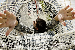
78 is our inclined netted chute system and like the DM- 76 provides a means of evacuation from height to ground level in a safe and controlled heat protected environment, however as the DM- 78 is an inclined chute evacuation times are slower than with the DM- 76 vertical chute system and require more physical exertion from the evacuees as they are descending the chute at an inclined angle and this requires a much longer chute to cover the inclined distance from the evacuation height to the ground.
SPECIFICATION BAKER STYLE INCLINED CHUTE SYSTEM
The DM-
The DM-
Enables a large volume of personnel to evacuate from the evacuation location without exposure to flame/heat or smoke. Transit time varies but each person will spend approx 60 seconds transiting the evacuation point to ground level dependent on chute length.
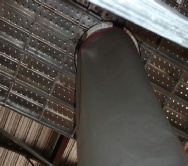
Designed to be low maintenance, offering evacuation solution that is available on demand. The floor mounted chute container is designed to offer additional protection from heat flux and ensures that the chute system is available in most fire related events.
The chute container is designed with an external mild steel cover that protects the chute and associated hardware, a dual set of access doors are provided that allows ease of access to the system.
An internal structural frame is provided and this houses all internal operational
components. The chute is stored at the front lower section of the container and is overhung ready for deployment in an emergency event. Very little day-
An anti-
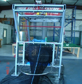
Purpose built Steel Frame:
The purpose built steel frame is hot dip galvanized after all welding and drilling has taken place. This allows for maximum weather resistance.
Outer Weather protection shell:
The outer shell is constructed of steel sheeting which incorporates a set of double access doors. These doors allow access to the deployment handle and entrance to the chute.
Full Operational Instructions:
Full operational instruction located in Section 3 of this manual. These instructions must be adhered to in all cases.
Note: Only Trained personnel should deploy and recover the chute system.
Operating the DM -
Open the double doors and remove the anti-
All evacuees must be trained prior to using the escape chute; this is covered under the training section. In all cases evacuees must enter the chute by lowering their body up to their waist into the chute keeping arms against their chest and legs in a crawl position. After fully entering the chute use arms to control descent speed, if you are descending to fast sit upwards and you descent speed will reduce.
The DM-
Please note:
The DM-
This procedure should be covered under the training provided while the RSS engineer is on-
Escape Chute Retrieval Procedure.
With the chute in the fully deployed position the following procedure needs to be followed to ensure proper retrieval of the escape chute.
1. Deploy the retrieval hook by operating the air winch located on top of the main structural frame. The hook must deploy all the way down the landing area of the escape chute. Note: a second person will be required to carry the hook to the landing area as the hook will be deployed vertically to the ground.
2. Secure the retrieval hook to the top of the exit gate.
3. Unlatch the exit gate from the landing area framework.
4. Operate the air winch in reverse to retrieve the chute.
5. Once the chute has been retrieved to its storage position secure in place by fitting the retaining ropes into the rope holders. Ensure the deployment wires are installed correctly under the retaining ropes to ensure correct deployment.
6. Replace the anti-
Monthly Service and Inspection Regime:
1. Check pneumatic pulley to ensure air supply is constant.
2. Make a visual inspection of u-
3. Check to ensure anti-
4. Check to ensure main overhead winch cable is not sagging or bowing.
5. Check that deployment wire and ropes are in the correct position
Lower Chute Mounting Frame:
6. Check to ensure main overhead winch cable is not sagging or bowing.
7. Check that deployment wire and ropes are in the correct position
Please contact us for full details on the DM-
For more information, please call and one of our representatives, we will be happy to answer any questions you may have.
Tel: 281 676 8008 Fax: 281 676 8033
Email: sales@rssusservices.com
Powered by Serif WebPlus